
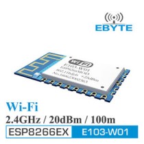
[ Interface ]:UART
[ Power ]:20dBm
[ Distance ]:100m
[ RF connector]:SMD
[ Frequency ]:2.4~2.4835 GHz (Default:2.4GHz)
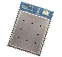
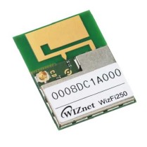
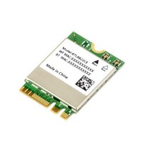
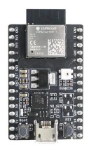
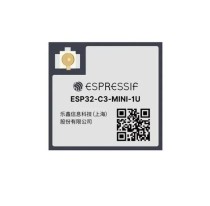
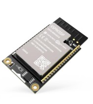
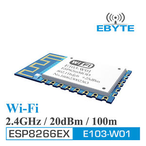
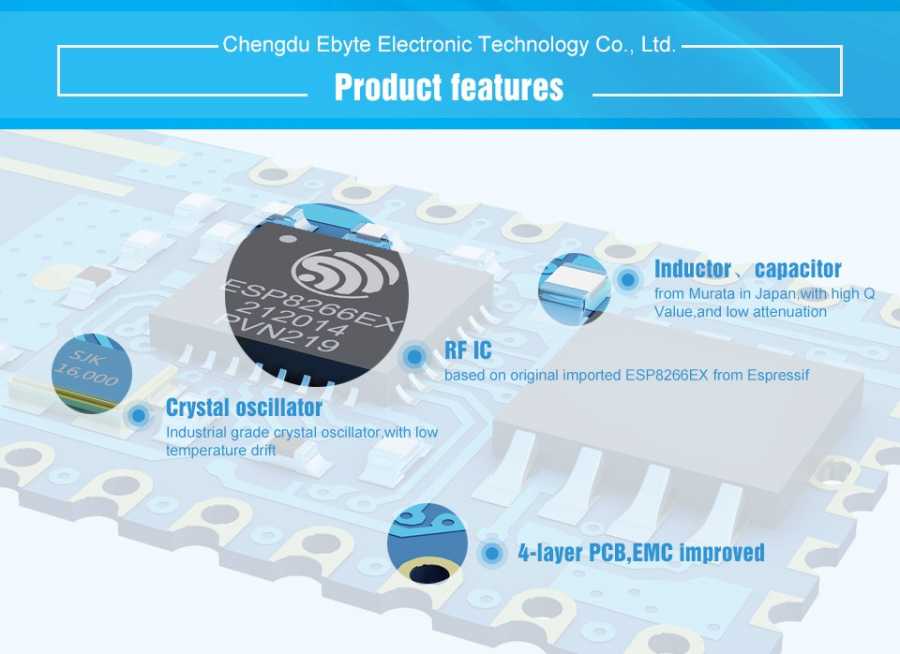
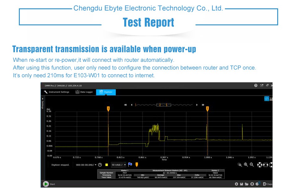
[ Feature ]:E103-W01 is 100mW (20dBm) UART-wi-fi module with competitive price. Small-size, embedded PCB antenna, operate at 2.4~2.4835GHz frequency band, with all those features, based on ESP8266EX from Espressif, transparent transmission is available, easy for user to operate
No. | Parameter item | Parameter value | Notes |
1 | RF chip | ESP8266EX | Espressif |
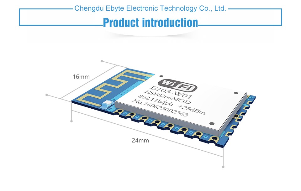
2 | Size | 16 * 24 * 3mm | With PCB antenna |
3 | Weight | 1.5g | With PCB antenna |
4 | PCB | 4-layer | Impedance debugging |
5 | Frequency Band | 2.4~2.4835 GHz |
|
6 | Connector | 2.00mm | SMD |
7 | Supply voltage | 3.0 ~ 3.6V DC | Note: the voltage higher than 3.6V is forbidden |
8 | Operation Range | 100m | Test condition:clear and open area& maximum power, height:> 2m |
9 | Transmitting power | 20dBm | About 100mW |
10 | AT support | Built-in intelligent processing | Can be read by AT command. |
11 | Wi-Fi version | 802.11 b/g/n |
|
12 | Communication interface | UART |
|
13 | Antenna type | PCB | 50Ω impedance |
14 | Operating temperature | -40 ~ +85℃ | Industrial-grade |
15 | Operating humidity | 10% ~ 90% | No condensation |
16 | Storage temperature | -40 ~ +125℃ | Industrial-grade |
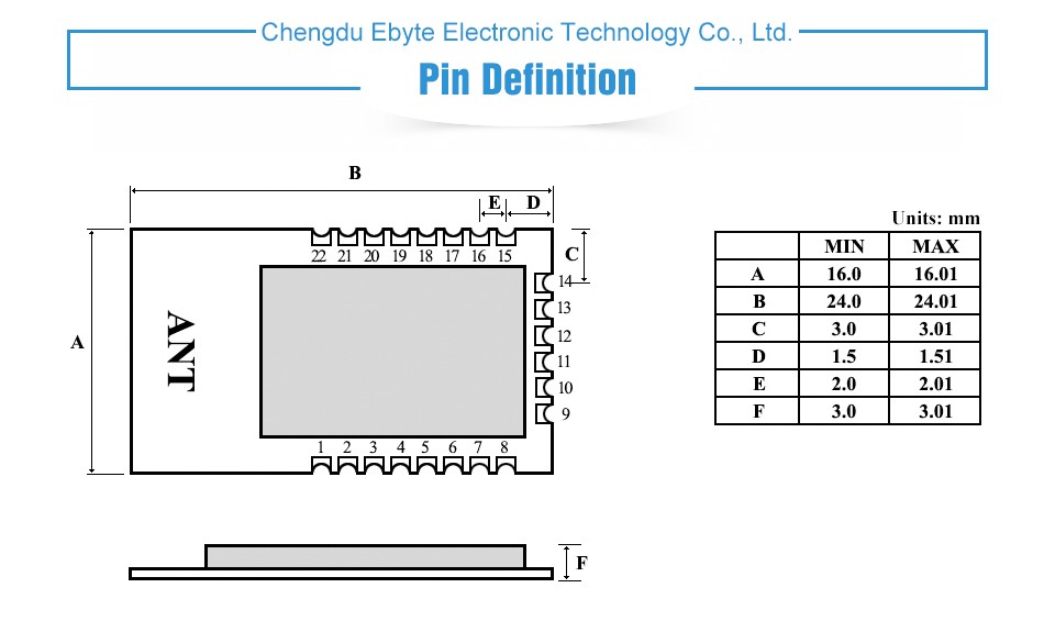
Pin | Name | Type | Function | |||
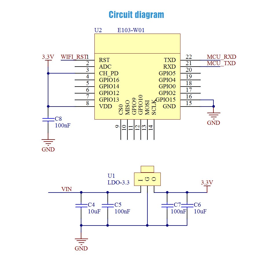
1 | RST | I | External reset signal (Low voltage level: Active) | |||
2 | ADC | I | ADC input pin | |||
3 | CH_PD | I | Module enable, need be pulled up | |||
4 | GPIO16 | I | module wake up(from deep sleep state), high level effectively | |||
5 | GPIO14 | IO | PWM1/GPIO14 | |||
6 | GPIO12 | IO | PWM0/GPIO12 | |||
7 | GPIO13 | IO | GPIO13 | |||
8 | VCC | - | VDC:3.0V~3.6V(above 300mA) | |||
9 | CSO | - |
For internal FLASH using, N/A. | |||
10 | MISO | - | ||||
11 | GPIO9 | - | ||||
12 | GPIO10 | - | ||||
13 | MOSI | - | ||||
14 | SCLK | - | ||||
15 | GND | - | GND | |||
16 | GPIO15 | I | GPIO15 | GPIO2 | GPIO0 | Boot |
17 | GPIO2 | I | 0 | 1 | 1 | Boot from FLASH |
18 | GPIO0 | I | 0 | 1 | 0 | Download firmware from UART |
19 | GPIO4 | IO | PWM2/GPIO4 | |||
20 | GPIO5 | IO | PWM3/GPIO5 | |||
21 | RXD | I | UART input pin, support AT command | |||
22 | TXD | O | UART output pin, support AT command | |||
GPIO2 is already been internal pulled up | ||||||
In transparent-transmission on power-up mode, GPIO2 will indicate the status of module. The module has connected a led to this pin. Users can get the status of the module by observing LED. Besides, you may connect GPIO2 to the external MCU. | ||||||
LED indication when module works in power-on transparent transmission mode: Intermittent double flash:cannot connect to AP access point. Intermittent single flash:connect to AP access point, but cannot connect to TCP server. Quench:connect to AP access point and TCP server. | ||||||
| Ürün Filtreleri | ||
|---|---|---|
| Tedarikçi Ürün Kodu | : | E103-W01 |
 E103-W01