


{{CMP.TITLE}}
{{CMP.DESCRIPTION}}
- Ürün Özellikleri
- İade ve Teslimat
- Ödeme Seçenekleri
- Yorumlar (0)
- Döküman
- Beni Ara
- Ek
-
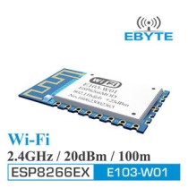
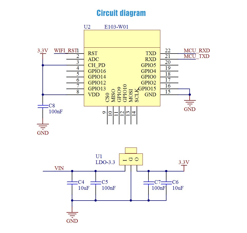
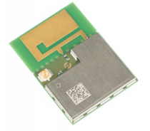
[ Model ]:E103-W01
[ Interface ]:UART
[ Power ]:20dBm
[ Distance ]:100m
[ RF connector]:SMD
[ Frequency ]:2.4~2.4835 GHz (Default:2.4GHz)
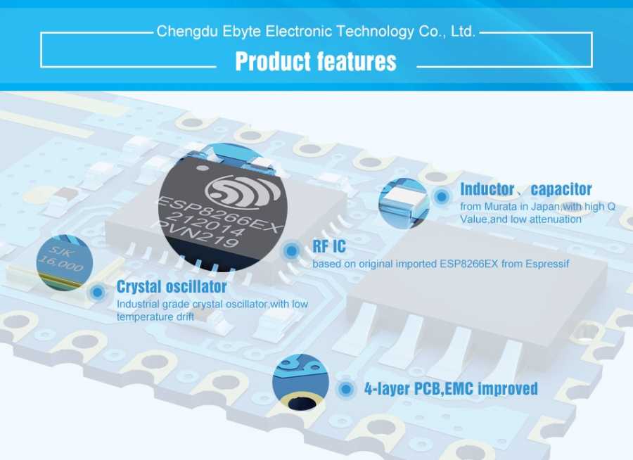
[ Feature ]:E103-W01 is 100mW (20dBm) UART-wi-fi module with competitive price. Small-size, embedded PCB antenna, operate at 2.4~2.4835GHz frequency band, with all those features, based on ESP8266EX from Espressif, transparent transmission is available, easy for user to operate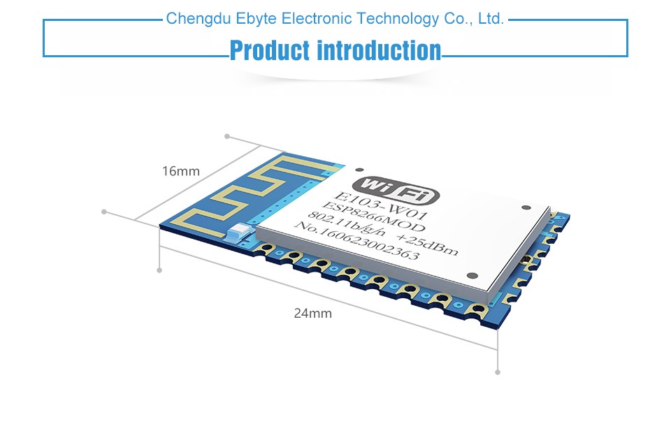
Electrical parameterNo.
Parameter item
Parameter value
Notes
1
RF chip
ESP8266EX
Espressif
2
Size
16 * 24 * 3mm
With PCB antenna
3
Weight
1.5g
With PCB antenna
4
PCB
4-layer
Impedance debugging
5
Frequency Band
2.4~2.4835 GHz
6
Connector
2.00mm
SMD
7
Supply voltage
3.0 ~ 3.6V DC
Note: the voltage higher than 3.6V is forbidden
8
Operation Range
100m
Test condition:clear and open area& maximum power, height:> 2m
9
Transmitting power
20dBm
About 100mW
10
AT support
Built-in intelligent processing
Can be read by AT command.
11
Wi-Fi version
802.11 b/g/n
12
Communication interface
UART
13
Antenna type
PCB
50Ω impedance
14
Operating temperature
-40 ~ +85℃
Industrial-grade
15
Operating humidity
10% ~ 90%
No condensation
16
Storage temperature
-40 ~ +125℃
Industrial-grade
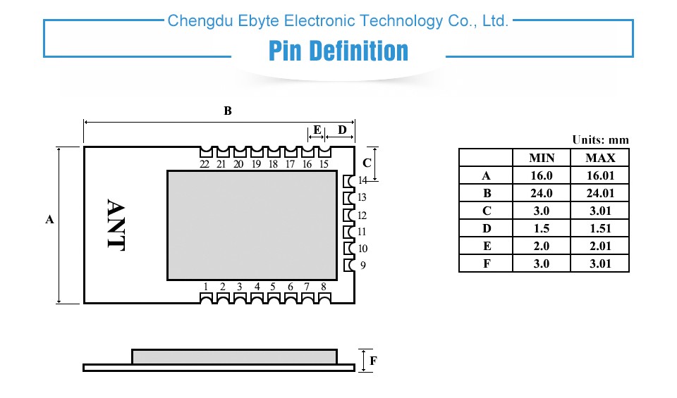
Pin
Name
Type
Function
1
RST
I
External reset signal (Low voltage level: Active)
2
ADC
I
ADC input pin
3
CH_PD
I
Module enable, need be pulled up
4
GPIO16
I
module wake up(from deep sleep state), high level effectively
5
GPIO14
IO
PWM1/GPIO14
6
GPIO12
IO
PWM0/GPIO12
7
GPIO13
IO
GPIO13
8
VCC
-
VDC:3.0V~3.6V(above 300mA)
9
CSO
-
For internal FLASH using, N/A.
10
MISO
-
11
GPIO9
-
12
GPIO10
-
13
MOSI
-
14
SCLK
-
15
GND
-
GND
16
GPIO15
I
GPIO15
GPIO2
GPIO0
Boot
17
GPIO2
I
0
1
1
Boot from FLASH
18
GPIO0
I
0
1
0
Download firmware from UART
19
GPIO4
IO
PWM2/GPIO4
20
GPIO5
IO
PWM3/GPIO5
21
RXD
I
UART input pin, support AT command
22
TXD
O
UART output pin, support AT command
GPIO2 is already been internal pulled up
In transparent-transmission on power-up mode, GPIO2 will indicate the status of module. The module has connected a led to this pin. Users can get the status of the module by observing LED. Besides, you may connect GPIO2 to the external MCU.
LED indication when module works in power-on transparent transmission mode:
Intermittent double flash:cannot connect to AP access point.
Intermittent single flash:connect to AP access point, but cannot connect to TCP server.
Quench:connect to AP access point and TCP server.
-
 RF Con./Coaxial SMT ML REC AU IPEX33,27 TL + KDVSepete Ekle
 -
 LTE-W-108144,18 TL + KDVSepete Ekle
 -
 WIFI Antenna / SMA/m 90-180 Degree173,01 TL + KDVSepete Ekle
-
 U.FL Connector Type, 802.11b Wi-Fi Module, Low Power1.242,15 TL + KDVSepete Ekle
 -
Teklif İsteyiniz
 WizFi250_CON(H)1.597,05 TL + KDVSepete Ekle
 -
Teklif İsteyiniz
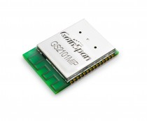 GS2101M887,25 TL + KDVSepete Ekle
 -
Teklif İsteyiniz
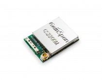 GS2200M887,25 TL + KDVSepete Ekle